Updated 12/30/05
Analog to Digital Instrument Cluster Conversion
The following is an instructional document on converting
a Blazer/Jimmy/Bravada/s10 pickup/etc. analog instrument cluster to
the digital instrument cluster.
|
WARNING: THIS DOCUMENT IS TO BE USED AS A GUIDELINE AND THE AUTHOR |
GENERAL INFORMATION
Written by Michael Akey - Copyright 2004. Revision 5.
This document can be reproduced freely as long as it is kept intact and proper recoginition is given to the original author.
BACKGROUND INFORMATION
Some useful information...
This vehicle used in this document is a 1991 Chevrolet Blazer
S-10/Tahoe edition with 4 wheel drive and an automatic transmission.
This guide WILL ONLY WORK FOR 1989-1994 MODELS!* If you have an S-10 Blazer that does not fit into that time period, or is a 1994 S-10 pickup, stop reading now.
All S-10 Blazers made in 1988 and earlier use a cable driven
speedometer, whereas the newer models receive an electronic signal from
a Vehicle Speed Sensor (VSS). Also, installing a VSS on an older model
S-10 Blazer is quite hard, and would require quite a bit of extra
wiring, and a small computer unit that interprets the VSS signal called
a Digital Ratio Adapter Control (DRAC) which is located next to your
ECM/PCM.
ALL analog instrument clusters use an 18-pin connector that is located in the lower left (looking from the front) of the cluster. Likewise, all digital instrument clusters use the 34-pin connector in the middle of the back of the cluster. GMC Typhoon/syclone instrument clusters are completely different and are not compatible with any other clusters.
* Not all 1994 S-10 Pickups are compatible with 1994 Blazer/Jimmy/Bravada clusters. Some are considered "second generation." Also, certain 87-88 model S-10s used a electronic speedometer and you should check your vehicle to see if it is. If it is, you can perform this swap.
MATERIALS
These are some of the required materials and tools. You may use others at your discresion.
THE CONNECTORS
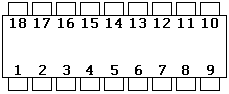
The 18-pin connector:
The Pinout:
| 1 | Panel lamp input | 10 | Anti-Lock indicator lamp |
| 2 | Hot (+12V) | 11 | Service Engine Soon indicator lamp |
| 3 | Generator indicator lamp | 12 | Hot (+12V from generator) |
| 4 | Upshift | 13 | DRL indicator |
| 5 | E. Brake light | 14 | Speedometer input |
| 6 | Coolant temp. input | 15 | Fasten seat belts lamp |
| 7 | right turn signal | 16 | High-Beam indicator lamp |
| 8 | Fuel sensor input | 17 | Ground |
| 9 | Oil pressure input | 18 | Left turn signal |
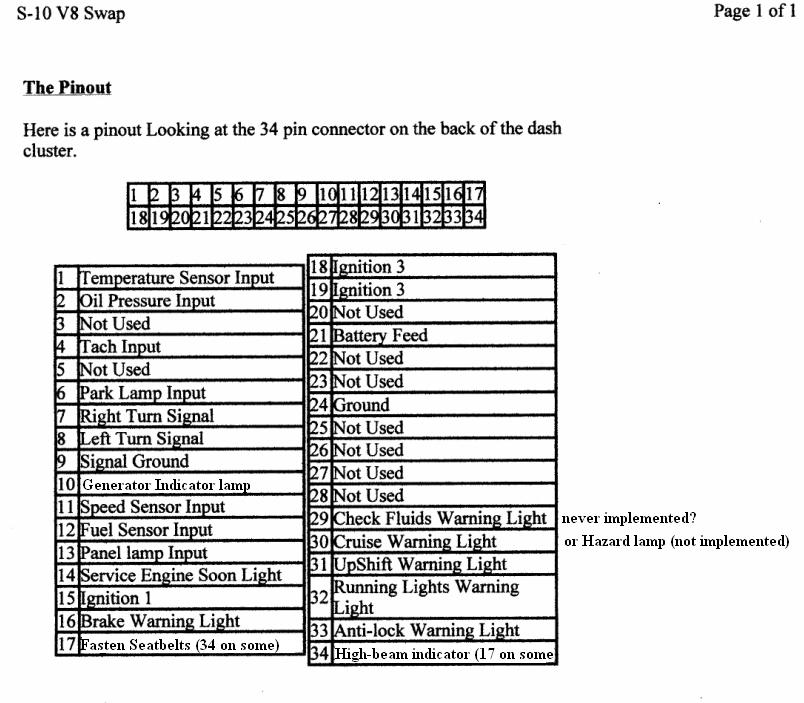
The 34-pin connector:
CLUSTER REMOVAL
The following are the instructions on how to remove the Instrument Cluster. Remember to store screws in a safe place.
Step 1:
Remove the fuse cover panel under the steering column.

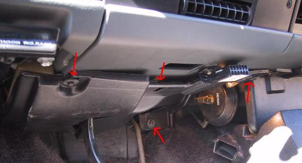
Step 2:
Remove the bottom plate by taking out the bolt above the gas pedal and
the 3 screws holding it on. The 3 screws can be removed by a flat head
screw driver or a 9/32in. nut driver.
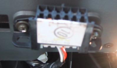
Step 3:
Remove the 2 screws that hold on the AL/DL connector to the bottom plate.
Step 4:
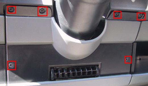
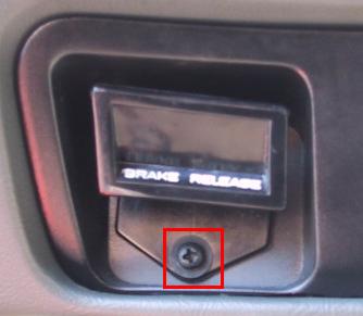
Remove all screws holding on the under steering column trim plate.
Don't forget to remove the Parking Brake screw. Also, to fully remove
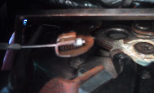
the trim, one must remove the ventilation tube and Parking Brake cable.
To remove the Parking Break cable, use a flat head screw driver to
compress the spring on the end of the cable and push the lever it is
connected to towards the rear of the vehicle.
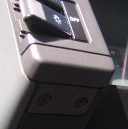
Step 5:
Remove the lighting controls plate. Be careful when removing the
connectors from the switches -- they may break easily. WARNING: light
switches ALWAYS have power running to them.
Step 6:
Loosen the Air conditioning vacuum hoses.
Step 7:
Remove A/C control plate screws.
Step 8:
Disconnect the blower switch cable, and grey wires. Then gently pull on
the entire assembly until it is about 6 inches out. This should allow
plently of space for the next step. If you feel the need to remove the
assembly completely, just pop off the clamps holding the temperature
selector switch and vacuum hoses. Be careful! Removing the clamps may
break the plastic, making it impossible to reassemble.
Step 9:
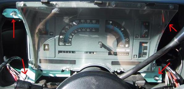
Remove the 4 bolts that hold on the bezel. (two more nuts on the
opposite side; use 10mm nut driver) You may want a "magnetic wand" or
some kind to hold on/fetch the bolt so you don't lose it (don't worry,
it won't go far anyway.)
Step 10:
Pull out bezel and flip to it's side so it is out of the way.
Step 11:
Remove the 4 fake nuts that are holding the cluster in.
Step 12:
Gently pull cluster out. Remember: Some person down at GM designed the
analog guages badly, making it hard to remove them. On the other hand,
the digital clusters address the issue of the hard removal, and leave
lots of space to deal with. Don't forget to detach the shifter cable
from the steering column if you have an automatic transmission!
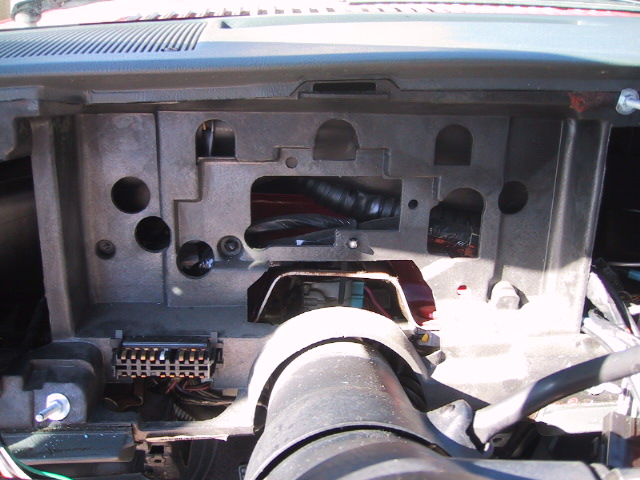
Hi-res picture of the analog cluster from the back.
OK! You're done. If you want to put it back together, just perform the removal steps in reverse order!
CONVERSION
NOW WOULD BE A GOOD TIME TO DISCONNECT THE NEGATIVE TERMINAL OF THE BATTERY!
Since most people do not have computers with internet access in their garages, printing out the wiring charts out might be a wise idea.
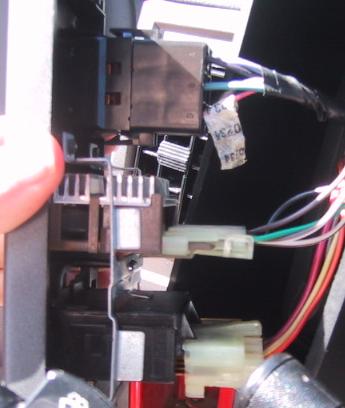
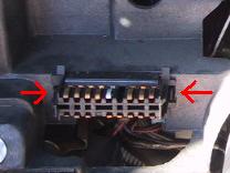
Step 1:
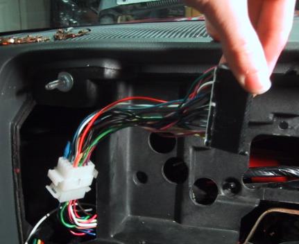
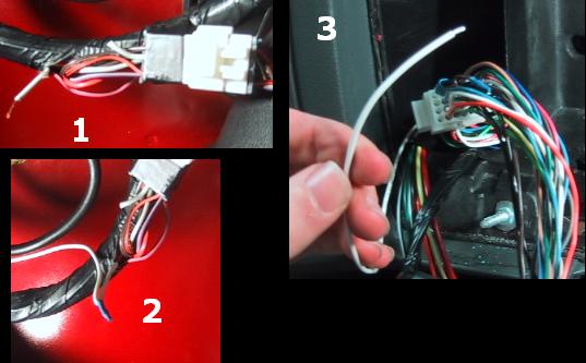
After the old cluster is removed and out of the way, unclip the 18-pin connector by pressing in on the 2 tabs (see below)
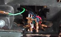
Step 2a:
There are many ways to do this step. This is also the longest and most
crucial step, so take your time. Attach the new 34-pin connector to the
old 18-pin connector using the wiring chart below. The method shown in
the following pictures is jsut one way to do this. You can just connect
all the wires up after clipping off the old 18-pin connector, make a
connector (like shown) so you can revert back to the analog cluster, or
how ever you choose. DO NOT REASSEMBLE DASH IMMEDIATLY AFTER COMPLETING
THIS PROCESS.
This table shows where the pins on the 34-pin connector connect to the 18-pin connector.
| 1 | 6 | 18 | 2 |
| 2 | 9 | 19 | same as 18 |
| 3 | n/a | 20 | n/a |
| 4 | see below | 21 | cig. outlet (orange) |
| 5 | n/a | 22 | n/a |
| 6 | 17(see below) | 23 | n/a |
| 7 | 7 | 24 | 17 |
| 8 | 18 | 25 | n/a |
| 9 | 17 | 26 | n/a |
| 10 | 3 | 27 | n/a |
| 11 | 14 | 28 | n/a |
| 12 | 8 | 29 | never used? |
| 13 | 1 | 30 | not implemented |
| 14 | 11 | 31 | 4 |
| 15 | 12 | 32 | 13 |
| 16 | 5 | 33 | 10 |
| 17 | 15 | 34 | 16 |
INFO: wire number 21 from the digtal cluster does not need to be
hooked up to a constant power source on 91-94 models. 89-90 are
required to have this hooked up to an always hot source such as the cig
outlet. This is to keep the trip data while your car is off.
MORE INFO: Pin 6 is for the dimming of the gauges while your headlights
are on. If you don't want them to dim, just ground the wire. If you do
want them to dim, wire it into the dark brown wire that goes to your
dimmer switch on your lights panel on the left of the bezel.
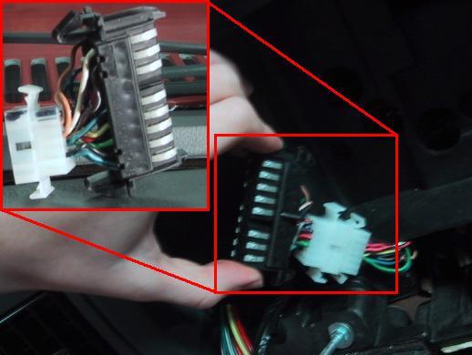
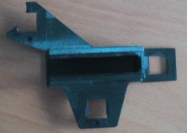
Conversion using a middle connector to allow usage of both analog and digital clusters(more time consuming.)
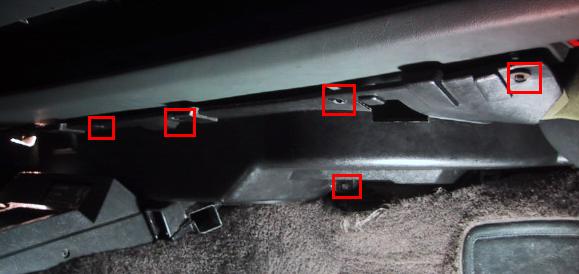
Step 2b:
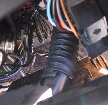
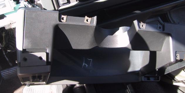
Before the connector can be fully installed, the tachometer must be
wired in. To do this, remove the lower panel under the dash on the
passenger side. Removing the floor shifter cover will make removing
this panel much easier.
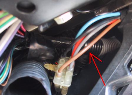
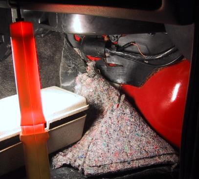
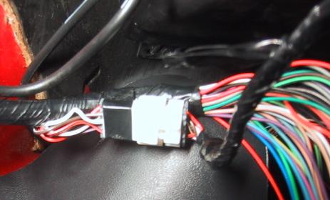
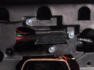
Now pull back the carpet as shown, and gently bring down the ECM wiring harness. Look for the white connector taped to the harness. Find the solid white wire going into it. If you had a digital insturment cluster factory installed, this wire would pass through the connector and go to your instrument cluster. Cut into that wire and use some 16 or 18 gauge wire and route it to the instrument cluster connector.
Step 3:
The next thing to do is to plug in your connector to the digital
cluster to make sure it works. Start the car and make sure the tach
also works. Once you have confirmed that everything is in order,
continue on. NOTE: When there is no signal to the oil/fuel gauges, they
will read as max/full.
Example photos:
Power On Self Test
Display on, engine off
Engine running
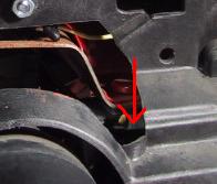
Step 4:
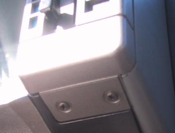
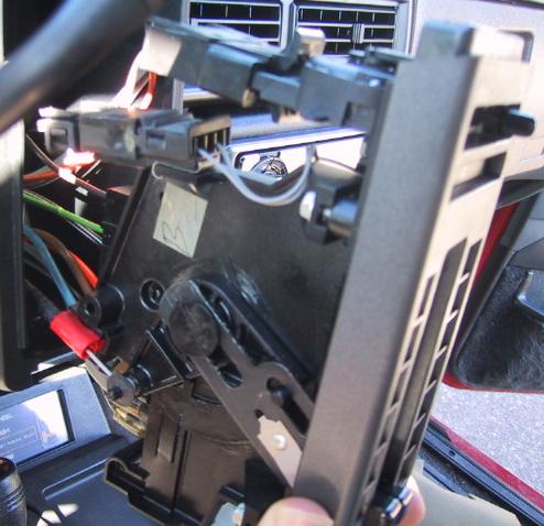
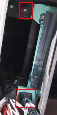
To finalize the process, you how have to slide the connector into the
plastic connector holder, shown below. Then carefully push it back into
the dash so that the 3 screw holes are behind the plastic of the dash
(see below). You may need to remove one of the wiring harness clips
that occupy the hole where the bottom screw goes. How you attach the
plastic holder is up to you, but remember to watch out for the wiring
harness. You do NOT want to accidentally put a screw into that -- this
would cause serious damage to your electrical system. I personally when
to the hardware store and picked up some new screws and bolts that were
about a half inch long, and some washers to hold the screws in on the
back side.
Step 5:
Install the cluster making sure to put the shifter cable through the
hole (see below). DO NOT FORCE IT. You may need to re-align the
connector so that it fits properly.
Step 6:
Check and make sure the cluster works once more, and then take the car
our for a spin and make sure the speedometer works. Then put everything
back together and you're done! Please feel free to email me with
questions using the email at the bottom of the page.
More info to come...
If this site has helped you out, I'd appreciate your help too. If you
have any instrument clusters you no longer need, and would like to get
rid of them, email me with the email at the bottom of the page. The
clusters (analog OR digital) given to me will be used for research
purposes in order to create and website with detailed information about
the different styles, and maybe customizations (like how to utilize
certain indicator lamps like cruise, hazard, check fluids) and modding
(for v8 engines?)... and other pages like this one!
If your DIGITAL gauges do not work properly, I don't repair them -- however, this person does. Also http://www.mrwhizard.com/ repairs them and will ship to Canada.
Thanks for visiting!
tester239 [at] comcast d0t net
![]()